| Class 150 – 400 | Class 600 – 2500 | ||||||||||||
| NPS | d1 | d2 | d3 | NPS | d1 | d2 | d3 | ||||||
| 150 | 300 | 400 | 600 | 900 | 1500 | 2500 | |||||||
| 1/2 | 23 | 33.3 | 44.4 | 50.8 | 50.8 | 1/2 | 23 | 33.3 | 50.8 | 60.3 | 60.3 | 66.7 | |
| 3/4 | 28.6 | 39.7 | 53.9 | 63.5 | 63.5 | 3/4 | 28.6 | 39.7 | 63.5 | 66.7 | 66.7 | 73 | |
| 1 | 36.5 | 47.6 | 63.5 | 69.8 | 69.8 | 1 | 36.5 | 47.6 | 69.8 | 76.2 | 76.2 | 82.5 | |
| 1.1/4 | 44.4 | 60.3 | 73 | 79.4 | 79.4 | 1.1/4 | 44.4 | 60.3 | 79.4 | 85.7 | 85.7 | 101.6 | |
| 1.1/2 | 52.4 | 69.8 | 82.5 | 92.1 | 92.1 | 1.1/2 | 52.4 | 69.8 | 92.1 | 95.2 | 95.2 | 114.3 | |
| 2 | 69.8 | 88.9 | 101.6 | 108 | 108 | 2 | 69.8 | 88.9 | 108 | 139.7 | 139.7 | 142.8 | |
| 2.1/2 | 82.5 | 101.6 | 120.6 | 127 | 127 | 2.1/2 | 82.5 | 101.6 | 127 | 161.9 | 161.9 | 165.1 | |
| 3 | 98.4 | 123.8 | 133.4 | 146.1 | 146.1 | 3 | 98.4 | 123.8 | 146.1 | 165.1 | 171.5 | 193.7 | |
| 3.1/2 | 111.1 | 136.5 | 158.8 | 161.9 | 158.7 | 3.1/2 | 111.1 | 136.5 | 158.7 | … | … | … | |
| 4 | 123.8 | 154 | 171.5 | 177.8 | 174.6 | 4 | 123.8 | 154 | 190.5 | 203.2 | 206.4 | 231.7 | |
| 5 | 150.8 | 182.6 | 193.7 | 212.7 | 209.5 | 5 | 150.8 | 182.6 | 238.1 | 244.5 | 250.8 | 276.2 | |
| 6 | 177.8 | 212.7 | 219.1 | 247.7 | 244.5 | 6 | 177.8 | 212.7 | 263.5 | 285.8 | 279.4 | 314.3 | |
| 8 | 228.6 | 266.7 | 276.2 | 304.8 | 301.6 | 8 | 228.6 | 266.7 | 317.5 | 355.6 | 349.3 | 384.1 | |
| 10 | 282.6 | 320.7 | 336.5 | 358.8 | 355.6 | 10 | 282.6 | 320.7 | 369.9 | 431.8 | 431.8 | 473 | |
| 12 | 339.7 | 377.8 | 406.4 | 419.1 | 415.9 | 12 | 339.7 | 377.8 | 454 | 495.3 | 517.5 | 546.1 | |
| 14 | 371.5 | 409.6 | 447.7 | 482.6 | 479.4 | 14 | 371.5 | 409.6 | 488.9 | 517.5 | 574.7 | … | |
| 16 | 422.3 | 466.7 | 511.2 | 536.6 | 533.4 | 16 | 422.3 | 466.7 | 561.9 | 571.5 | 638.1 | … | |
| 18 | 479.4 | 530.2 | 546.1 | 593.7 | 590.5 | 18 | 479.4 | 530.2 | 609.6 | 635 | 701.7 | … | |
| 20 | 530.2 | 581 | 603.2 | 650.9 | 644.5 | 20 | 530.2 | 581 | 679.5 | 695.3 | 752.4 | … | |
| 24 | 631.8 | 682.6 | 714.4 | 771.5 | 765.2 | 24 | 631.8 | 682.6 | 787.4 | 835 | 898.5 | … | |
| NPS | d1 | d2 | 150 | 300 | 400 | NPS | d1 | d2 | 600 | 900 | 1500 | 2500 | |
| d3 | d3 | ||||||||||||
General notes:
- Dimensions are in millimeters unless otherwise indicated.
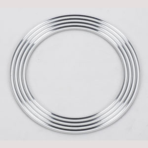
- Images shows Grooved Gaskets with Covering Layer and Centering Ring.
- d1 = Inside diameter.
- d2 = Outside diameter.
- d3 = Outside diameter of centering ring.
- Thickness (t) specified by customer.

